Read the forum code of contact
By: - 27th September 2013 at 21:19 Permalink - Edited 1st January 1970 at 01:00
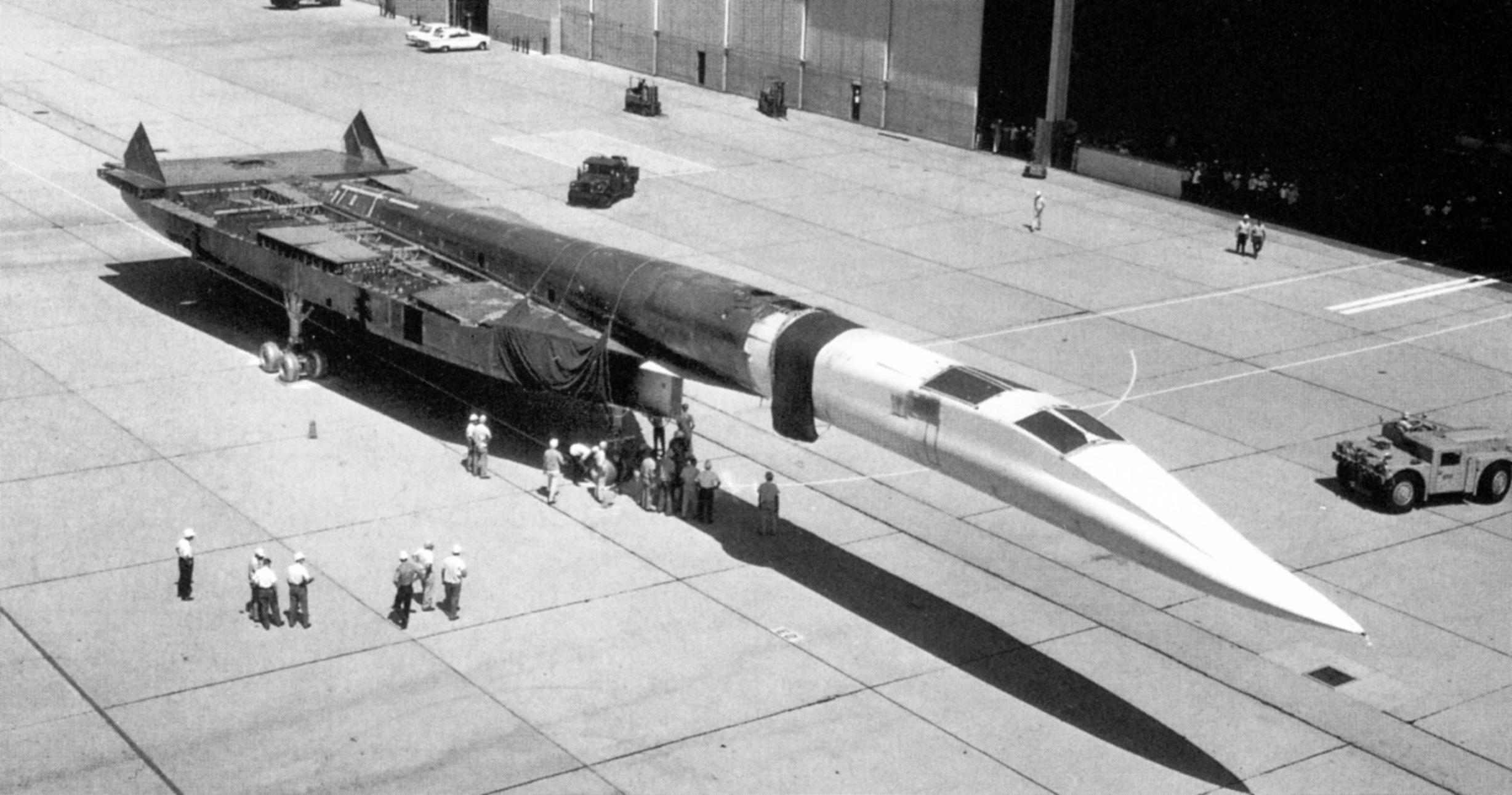
From my own book, this NAA pic of AV/1 under construction, before the wing panels were fitted. AV/2 was the same up to this point[ATTACH=CONFIG]221304[/ATTACH]
By: - 28th September 2013 at 05:59 Permalink - Edited 1st January 1970 at 01:00
Very useful Graham - thanks. Certainly confirms the aircraft is still flat across the centre. Looks like the joint is pretty much as I thought, tapering silightly towards the nose, and then possibly straightening ?
By: - 28th September 2013 at 06:31 Permalink - Edited 1st January 1970 at 01:00
Another NAA pic that I didn't use in the book was this one.... shows the back end along with structural details. [ATTACH=CONFIG]221306[/ATTACH]

By: - 28th September 2013 at 06:51 Permalink - Edited 1st January 1970 at 01:00
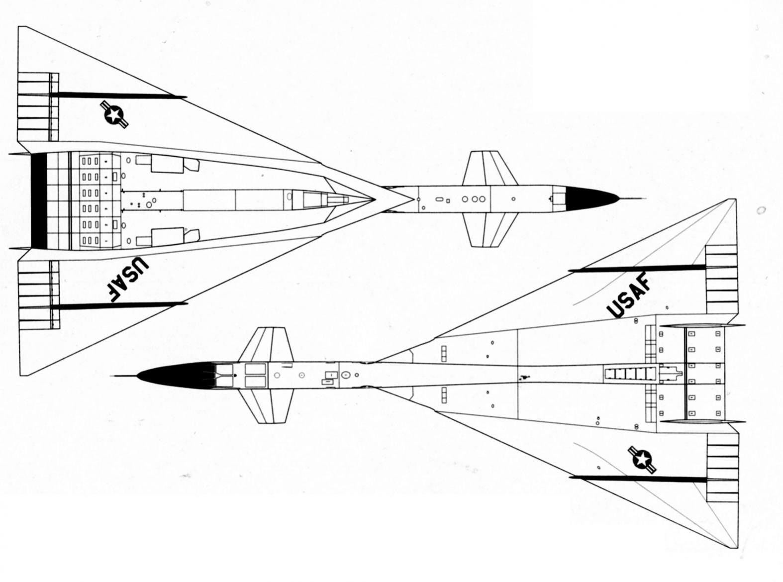
These pair of NAA views show the break line - the wing join stops behind the air intakes [ATTACH=CONFIG]221307[/ATTACH]
By: - 1st October 2013 at 10:57 Permalink - Edited 1st January 1970 at 01:00
Now can we have a head on view please showing 5 degrees dihedral on each wing? I am finding it difficult to understand why NAA put dihedral on a delta wing. I take it we are discussing the wing here and not the variable tips as you have drawn attention to the wing join line.
I quote from X-Plane Crashes page 62. "NASA wind-tunnel studies led engineers at North American to build the second XB-70 with an additional five degrees of dihedral on the wings." Additional to what? Was the wing dihedral zero degrees before?
Just to cloud the waters even more the book captions a photo of AV-2 on rollout thus: "AV-2 was distinguishable from its sister ship by a black nose-chin radome and a more pronounced wingtip dihedral." Wingtip now not wing dihedral. Of course the wingtips don't have dihedral at all. They have anhedral meaning they are bent down like the Lippisch ears on a Heinkel He 162. Could it be perhaps that the second prototype's wingtips had 5 degrees more bend down than the first prototype's and that this had nothing to do with the dihedral of the wing?
Please put me out of my misery.
By: - 2nd October 2013 at 01:56 Permalink - Edited 1st January 1970 at 01:00
Of course the wingtips don't have dihedral at all. They have anhedral meaning they are bent down like the Lippisch ears on a Heinkel He 162. Could it be perhaps that the second prototype's wingtips had 5 degrees more bend down than the first prototype's and that this had nothing to do with the dihedral of the wing?
Please put me out of my misery.
Well, the start of ypour relief is to realize that the wingtips were not fixed... they were parallel to the rest of the wing on the ground and in flight, the XB-70 could lower the outer wing sections either 25 degrees for flying from 300 knots to Mach 1.4, or a severe 65 degrees for speeds from Mach 1.4 to Mach 3+.
Here is a pic of AV/2 (tail number 20207) at take-off:


By: - 2nd October 2013 at 06:31 Permalink - Edited 1st January 1970 at 01:00
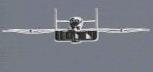
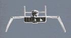
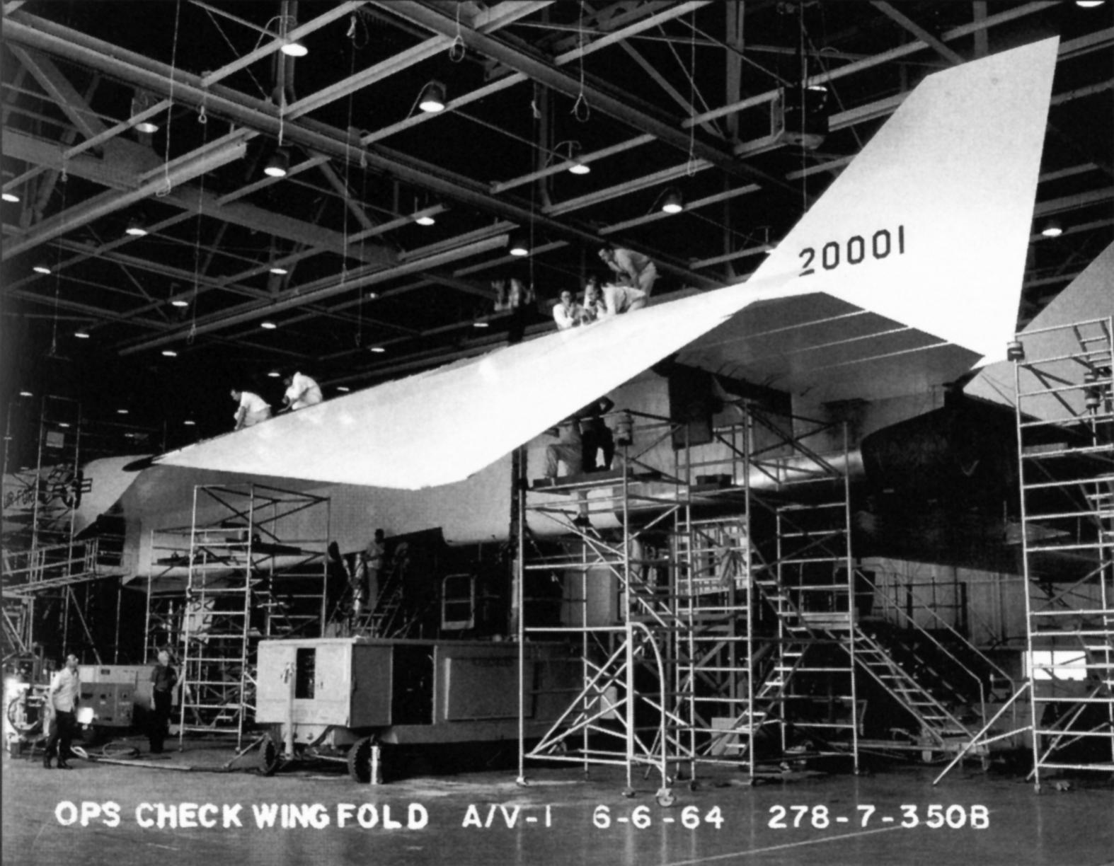
I've always been amazed by these two picts of the testing of the wing fold...!
[ATTACH=CONFIG]221461[/ATTACH][ATTACH=CONFIG]221462[/ATTACH]

By: - 2nd October 2013 at 10:04 Permalink - Edited 1st January 1970 at 01:00
Thanks. Yes I get that but still cannot fathom the 5 degree wing dihedral which is claimed for the second prototype. The wing looks dead straight to me in the head on drawing but difficult to tell because of the conical camber leading edge.
By: - 2nd October 2013 at 14:32 Permalink - Edited 1st January 1970 at 01:00
My take on it is there is dihedral ( polyhedral ? ) on the wing inner sections outboard on the engine pod, and that the tips lay parrallel to this when up
By: - 2nd October 2013 at 19:51 Permalink - Edited 1st January 1970 at 01:00
I don't have a copy of Graham Simons's book but the publication, Valkyrie - North American's Mach 3 Superbomber, ISBN 1-58007-072-8 is crammed full of facts, images and schematics. I inherited my Father's copy and must say it has been an incredible read.
By: - 2nd October 2013 at 20:03 Permalink - Edited 1st January 1970 at 01:00
I've dug through the image file, and come up with this one. It shows AV2 under contraction - the wing panels are outboard of the lines of men working wing.fuse join.[ATTACH=CONFIG]221482[/ATTACH]

By: - 3rd October 2013 at 10:17 Permalink - Edited 1st January 1970 at 01:00
I had a trawl through Flight Global and came up with these two. The first link is for Flight International 25 June 1964. Scroll down to the paragraph headed Leading Facts. There it is said that the outer wing panels appear to have dihedral but it is an optical illusion. However the article deals with the first prototype and JagRigger's question concerns whether the second prototype had dihedral.
The second link is for Flight International 17 June 1965 featuring the roll out of the second prototype. The caption refers to the wing-tips having increased anhedral of 25 degrees. I am still not convinced the wing had dihedral at all on either prototype.
http://www.flightglobal.com/pdfarchive/view/1964/1964%20-%201915.html?search=XB--70 Valkyrie
http://www.flightglobal.com/pdfarchive/view/1965/1965%20-%201854.html?search=north american xb-70
By: - 3rd October 2013 at 17:12 Permalink - Edited 1st January 1970 at 01:00
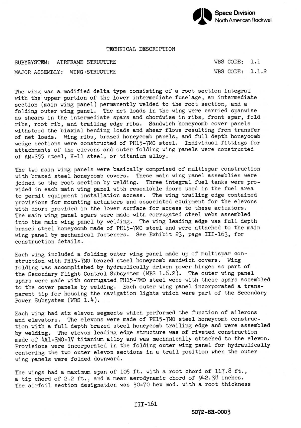
Since ‘skyshooter’ clearly refuses to believe what he is being advised here, I went back to some of my primary source documentation I used in my Pen & Sword book on the XB-70, viz: ‘B-70 Aircraft Study Final Report Volumes 1-4’ produced by L J Taube, Study Manager, North American Rockwell, dated April 1972. This is a massive work, totally well over 2000 pages.
Within Volume 3 SD72–SH-0003, pages III-161, III-162, there is a description of the airframe and wing structure, which I have scanned and attached. Although details are on both pages, the key part is on page 162, and I quote: 'The dihedral of the wing on air vehicle No.2 was 5 degrees while air vehicle No.1 had a dihedral of zero degrees. (This was a development change which occurred too late to incorporate on air vehicle No.1'
[ATTACH=CONFIG]221534[/ATTACH][ATTACH=CONFIG]221535[/ATTACH]

By: - 3rd October 2013 at 20:30 Permalink - Edited 1st January 1970 at 01:00
Well that is proof positive. Five degrees should be visually obvious but is not apparent in photos I have seen. Ideally one would like to see a rear view showing the wing trailing edge line. Bager 1968's take off picture does show some up sweep towards the tips.
Thanks Graham for posting the Report extract. I was not refusing to believe what I had been advised. I was not being persuaded by the submissions. I am not "skyshooter" either.
Posts: 460
By: JagRigger - 27th September 2013 at 18:55
OK - no one on the modelling forum I also frequent seems to know, so.......
Ship No2 was built with 5 degrees dihedral. Apparantly this was done by fitting a wedge at the wing attachment point - but just where was the break for the wing fit ? Is it the doglegged panel line outboard of the fins, meaning the trailing edge between is flat ?